

- #INVERTER GENERATOR SCHEMATIC DIAGRAM HOW TO#
- #INVERTER GENERATOR SCHEMATIC DIAGRAM PDF#
- #INVERTER GENERATOR SCHEMATIC DIAGRAM MANUAL#
- #INVERTER GENERATOR SCHEMATIC DIAGRAM TRIAL#
#INVERTER GENERATOR SCHEMATIC DIAGRAM PDF#
I'll see if I can find the manual, scan the theory of operation & electrics sections and have a PDF for the curious.
#INVERTER GENERATOR SCHEMATIC DIAGRAM TRIAL#
It'd be neat to have jumper plugs to intercept all signals in and out of the Honda modules and some signal pick-ups surgically installed through the encapsulation but that is a lot of trial and error and a LOT of analog/digital sensors, essentially reinventing the wheel! involves monitoring signals requiring conductor/trace access to component parts cast deeply in mil-spec encapsulation. Intercepting the overload & over temp shut-down or current limiting commands, stability/quality of input power signals.
#INVERTER GENERATOR SCHEMATIC DIAGRAM MANUAL#
Way back I glommed onto a Eu3000 shop manual with the point to point troubleshooting procedures just for the curiosity of investigating multi-purpose inverter built in/around a Honda inverter generator.ģ60-400V DC is not something to be casual with a DC boost module scabbed onto the Eu cover with wire runs insulated in 2000V silicone could accomplish transmission but then there is isolating the Honda alternator & diode sections without any chance of stray/leakage voltage, 400VDC likes to creep & arc, that would be a challenge even with solid-state switching. If it falls short, more solar panels should fix it. I have yet to find out how well it will go through winter. My system supplies around 75% to 80% of consumption in summer. If you have grid power available, a battery is really going to be uneconomic, unless you have very high night time loads. But I use the grid as my night time battery.Ī 360 volt lithium battery from a Chevy Volt would be one possible way. It would be pretty easy to add a wind turbine, standby generator, or hydo to it.Ī battery is difficult because of the rather high dc voltages required. Its very simple, and there is no requirement to frequency lock the inverter to the grid, so the inverter is simple too.Īs its not grid tie, and feeds nothing back, the power utilities don't know I have this. That is how it runs at night.ĭuring the day, all the dc power comes from solar panels at a high voltage, and there is no power drawn from the grid. I am doing something similar with a mains transformer rectifier, to generate a high dc voltage that drives an inverter direct to generate a pure sine wave. electronicshelpcare.I have never seen this anywhere else either, but its an excellent idea.ĭoing it all at high dc voltage and low current means the efficiency will be very high. If you like electronics please visit our another post. If you want another post then please visit our website. Transistor circuit diagram of 2sa1943 and 2sc5200īuild a Transformer or construction of the transformer. Transistor circuit diagram of 2sc5200 and 2sa1943.
#INVERTER GENERATOR SCHEMATIC DIAGRAM HOW TO#
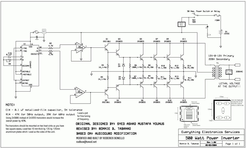
How to add more transistor to the amplifier? STK4141 and STK4121 datasheet.Īudio amplifier circuit diagram 8 transistors. How to make half wave to center tap transformer? Transistor circuit diagram using A1941 and C5198. How to make an amplifier using transistor TTC5200? how to make a voltage regulator using a transistor? How to make a music light show? transistor circuit diagram of 2sa1943 and 2sc5200. How to make inverter for an amplifier? How to make the sub amplifier in an easy way? How To Make Inverter unlimited Watt 2n3055 Transistor? Low pass filter for Subwoofer with 4558d IC. 2sc5200 2sa1943 amplifier circuit diagram PCB. Mini amplifier circuit diagram using lm380. How to make an inverter at home 10 watts. Low pass filter circuit diagram for the subwoofer? How to make turbo bass for amplifier circuit diagram?Īmplifier circuit diagram TDA7294 240W Stereo. and for secondary, we can see a Diode and 2 capacitors for making the voltage. The 2n3055 piece and 5watts 220 or 330 register 2 pieces. we use 2 transistor and 2 resistors only. after we get 50-0-50 voltage.It’s so easy to make this. In this Diagram we can see that we use a 12 voltage battery.


 0 kommentar(er)
